DIY Induction Heater Plans: A Comprehensive Guide to Building Your Own
Induction heating is a fascinating technology that uses electromagnetic fields to heat conductive materials without direct contact. Whether you’re a hobbyist, maker, or engineer, building your own induction heater can be a rewarding project. It offers a hands-on way to understand electromagnetism, power electronics, and thermal management. This guide provides detailed DIY induction heater plans, covering everything from the basic principles to step-by-step assembly. By the end, you’ll have the knowledge to construct a reliable induction heater for tasks like metal hardening, brazing, or even cooking experiments. Let’s dive into the world of DIY induction heating.
What is an Induction Heater and How Does It Work?
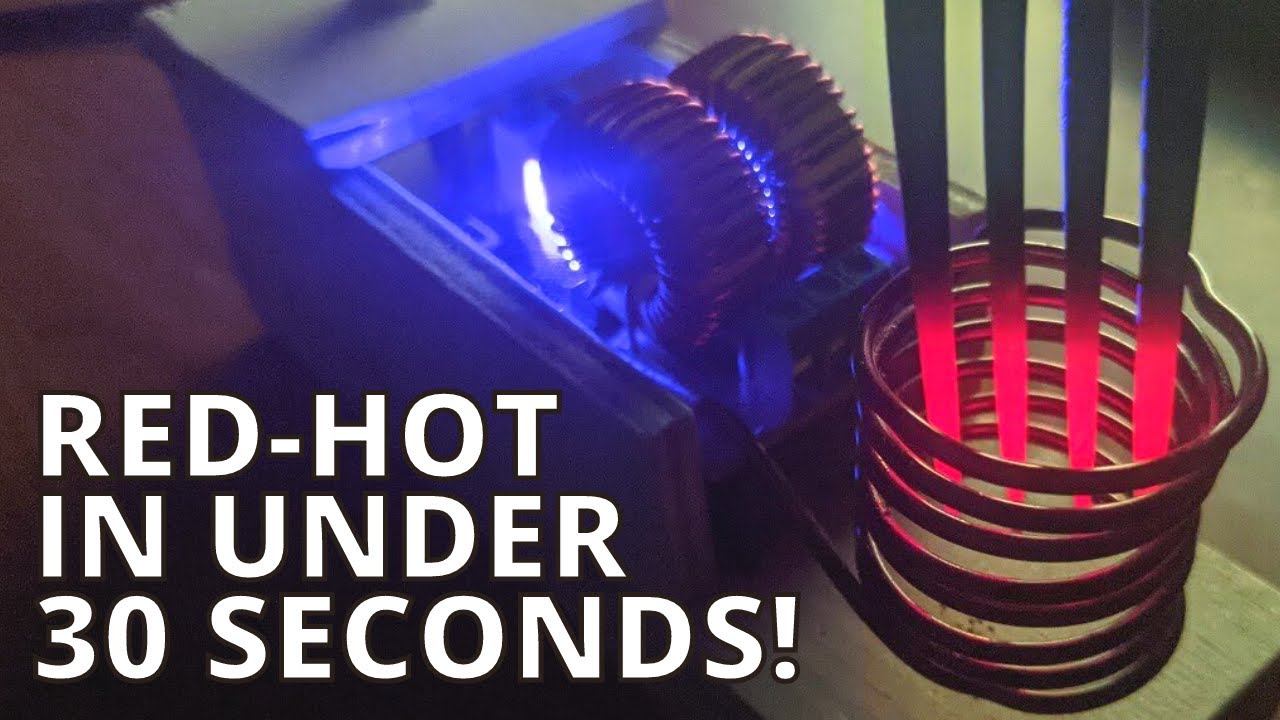
An induction heater operates on the principle of electromagnetic induction. When a high-frequency alternating current (AC) passes through a coil, it generates a rapidly changing magnetic field. If a conductive object, such as a metal workpiece, is placed inside or near this coil, eddy currents are induced within the object. These currents flow through the resistance of the metal, generating heat through Joule heating. For ferromagnetic materials, additional heat is produced by hysteresis losses. The frequency typically used in DIY induction heaters ranges from 20 kHz to over 100 kHz. The higher the frequency, the shallower the heating penetration, which is ideal for surface hardening. Understanding this basic principle is crucial for designing an efficient induction heater. The power output, coil geometry, and workpiece material all affect heating performance. Our DIY plans will focus on a resonant circuit topology that maximizes energy transfer.
Key Components for Your DIY Induction Heater
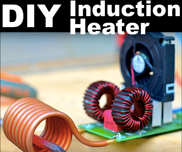
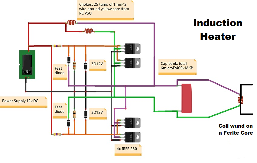
To build a functional induction heater, you’ll need several key components. The heart of the circuit is a high-frequency inverter, often built around a half-bridge or full-bridge topology using MOSFETs or IGBTs. A popular choice for DIYers is the ZVS (Zero Voltage Switching) driver, which uses a resonant tank circuit for efficiency. Other essential parts include:
- Copper coil (work coil): Typically made from thick copper tubing or Litz wire to reduce skin effect losses. The coil’s shape and number of turns determine the magnetic field strength and frequency.
- Capacitor bank: Resonant capacitors (polypropylene or C0G) that form an LC circuit with the work coil. The capacitance value must match the coil inductance to achieve resonance.
- Power supply: A DC power source, usually between 12V and 48V for low-power units, or higher for industrial-style heaters. A heavy-duty transformer and rectifier may be needed for high power.
- Gate driver circuit: To drive the MOSFETs with appropriate voltage levels and isolation.
- Heat sink and cooling: MOSFETs and the work coil generate significant heat. Forced air cooling or water cooling is recommended for continuous operation.
- Control electronics: A microcontroller or timer for pulse control, plus safety features like overcurrent protection.
Selecting quality components is critical for reliability. Use high-voltage, low-ESR capacitors and MOSFETs with low Rds(on). The work coil should be wound with care to avoid short circuits between turns.
DIY Induction Heater Circuit Design Overview
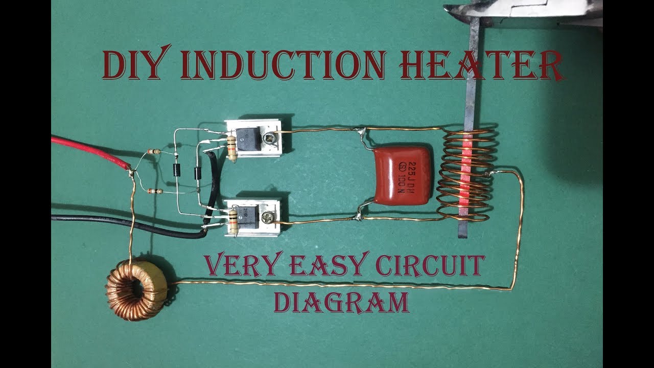
The most common DIY induction heater circuit is the ZVS driver, which is simple and robust. It uses a resonant LC tank where the work coil and capacitor bank determine the operating frequency. The circuit self-oscillates due to positive feedback from a secondary winding or a current transformer. A typical ZVS topology includes two MOSFETs (e.g., IRFP250N) connected in a half-bridge configuration, with a center-tapped inductor for gate drive. The resonant capacitor is placed in parallel with the work coil. A DC power supply feeds the center tap of the primary inductor. The MOSFETs alternately switch, causing the LC tank to oscillate at resonance. The output voltage across the coil can be several hundred volts peak-to-peak, depending on the supply voltage and Q factor. For higher power, a full-bridge design with four MOSFETs can be used, but the ZVS driver is usually sufficient for hobbyist applications up to 1 kW. Our plans include a detailed schematic with component values for a 500W unit operating at 50 kHz.
Step-by-Step Assembly Instructions
- Prepare the work coil: Wind 5-8 turns of 6mm copper tubing around a cylindrical form (e.g., PVC pipe) with a diameter of 2-3 inches. Leave leads for connections. Optionally, use Litz wire for efficiency.
- Assemble the capacitor bank: Solder multiple polypropylene capacitors (e.g., 0.47 µF each) in parallel to achieve the desired total capacitance. For a 50 kHz resonant frequency with a 10 µH coil, you need about 0.5 µF. Adjust as needed.
- Mount MOSFETs on heat sinks: Use thermal paste and insulate the MOSFETs from the heat sink with mica pads if necessary.
- Build the gate drive transformer: Wind a small ferrite core with two identical secondary windings (e.g., 10 turns each) and a primary winding (20 turns). This provides isolated gate signals.
- Solder the main circuit board: Connect the MOSFETs, capacitors, gate drive transformer, and bias resistors according to the schematic. Use thick traces for high current paths.
- Connect the power supply: Attach a DC power source (24V recommended for first test) through a fuse and switch. Ensure proper polarity.
- Test the circuit: Power up briefly and check for oscillation using an oscilloscope or a neon bulb near the coil. Adjust capacitor values if frequency is off.
- Enclose the system: Place the circuit in a metal enclosure with ventilation. Add a fan for cooling.
Tuning and Testing Your Induction Heater
After assembly, tuning is crucial for efficient operation. The resonant frequency of the LC tank must match the switching frequency. Use an oscilloscope to measure the voltage across the coil; a clean sine wave indicates proper resonance. If the waveform is distorted, adjust the capacitor bank or coil turns. You can also add a small variable capacitor for fine-tuning. Test with a workpiece: place a steel bolt or nail inside the coil; it should heat up within seconds. Monitor the MOSFET temperatures; if they get too hot, improve cooling or reduce duty cycle. The power output can be controlled by varying the DC supply voltage or using a PWM signal on the gate drive. For consistent results, incorporate a feedback loop that adjusts frequency to maintain resonance as the workpiece heats up.
Safety Considerations When Building an Induction Heater
Safety is paramount when working with high voltages and currents. Always work in a well-ventilated area and use insulated tools. The voltage across the work coil can reach hundreds of volts, posing a shock hazard. Ensure all connections are secure and insulated. Use a fuse on the mains input to protect against short circuits. Never touch the work coil while it is energized, as it can cause burns or RF burns. Wear safety glasses to protect against flying sparks or molten metal. If using water cooling, ensure there is no water leakage near electronics. Finally, keep a fire extinguisher nearby, especially when heating flammable materials. Building an induction heater is a safe project if you follow these precautions.
Advanced Modifications and Upgrades
Once you have a working induction heater, you can explore advanced upgrades. Add a microcontroller-based frequency tracking system (e.g., using a PLL) to maintain resonance automatically. Increase power by upgrading to higher-rated MOSFETs and a larger power supply. Implement a temperature control loop using a thermocouple to regulate heating cycles. For specific applications like brazing, design a custom coil shape that conforms to the workpiece. You can also integrate a display showing power, frequency, and temperature. Another popular upgrade is adding a soft-start circuit to reduce inrush current. With these modifications, your DIY induction heater can match commercial units in performance.
Frequently Asked Questions
What is the best frequency for a DIY induction heater?
The optimal frequency depends on the workpiece size and material. For small parts (e.g., screws), 50-100 kHz works well. For larger objects, lower frequencies (20-30 kHz) provide deeper heating. Our plans use 50 kHz as a good balance.
Can I use a computer power supply for the induction heater?
Yes, a 12V or 24V PC power supply can be used for low-power experiments, but ensure it can deliver sufficient current (e.g., 20A for 500W). For higher power, a dedicated variable DC supply is recommended.
Why are my MOSFETs getting hot quickly?
MOSFET overheating can be due to poor heat sinking, insufficient gate drive, or operating off resonance. Check that the circuit is tuned properly and that the gate signal is clean. Also, ensure the MOSFETs are adequately rated for the current.
Can I heat aluminum with an induction heater?
Aluminum is non-magnetic and has low resistivity, so it is harder to heat. However, with a high-power induction heater (1 kW+) and proper frequency tuning, aluminum can be heated. You may need a higher frequency (100 kHz+) for small aluminum parts.
Is it legal to build a DIY induction heater?
Yes, building an induction heater for personal use is legal in most countries. However, be aware of radio frequency interference (RFI) regulations. The circuit can radiate noise; using a shielded enclosure and ferrite beads can help.
Building your own induction heater is a challenging but immensely satisfying project that deepens your understanding of electronics and thermodynamics. With these detailed DIY induction heater plans, you can create a functional tool for a variety of heating applications. Start with a low-power prototype, experiment with different coil designs, and gradually upgrade to higher power. Always prioritize safety and enjoy the process of making something that harnesses the power of electromagnetism. Happy building!